My major project was a step up from my minor in a sense that it was no longer based on the Duemilanove but instead by using the Lilypad Arduino and putting it into fabric.
Notes about the Lilypad arduino from the arduino.cc site:
Overview
The LilyPad Arduino is a microcontroller board designed for wearables and e-textiles. It can be sewn to fabric and similarly mounted power supplies, sensors and actuators with conductive thread. The board is based on theATmega168V (the low-power version of the ATmega168) or the ATmega328V. The LilyPadArduino was designed and developed by Leah Buechley and SparkFun Electronics.
Summary
Warning: Don't power the LilyPad Arduino with more than 5.5 volts, or plug the power in backwards: you'll kill it.
| Microcontroller | ATmega168V or ATmega328V |
| Operating Voltage | 2.7-5.5 V |
| Input Voltage | 2.7-5.5 V |
| Digital I/O Pins | 14 (of which 6 provide PWM output) |
| Analog Input Pins | 6 |
| DC Current per I/O Pin | 40 mA |
| Flash Memory | 16 KB (of which 2 KB used by bootloader) |
| SRAM | 1 KB |
| EEPROM | 512 bytes |
| Clock Speed | 8 MHz |
Power
The LilyPad Arduino can be powered via the USB connection or with an external power supply.
If an external power supply is used, it should provide between 2.7 and 5.5 volts. This can come either from an AC-to-DC adapter (wall-wart) or battery. Again, don't power the LilyPad Arduino with more than 5.5 volts, or plug the power in backwards: you'll kill it.
Physical Characteristics
The LilyPad Arduino is a circle, approximately 50mm (2") in diameter. The board itself is .8mm (1/32") thick (approximately 3mm (1/8") where electronics are attached).
Washability
Wash at your own risk - we do ;). We recommend washing projects by hand with a mild detergent. Drip dry. Make sure you remove your power supply first!
Connecting the LilyPad Arduino
To program the LilyPad Arduino, you need to connect it to your computer. The SparkFun FTDI Basic Breakout plugs into the 6-pin male header on the newest version of the LilyPad. Use a USB MiniB cable to connect the FTDI basic breakout to your computer. You can also use an FTDI USB-TTL Serial cable.
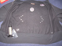
Setup: Jacket, Lilypad Arduino, LED's, battery holder, push buttons, conductive thread, sewing needle, contre crayon & lots of time.
Firstly, i drew in where everything was going to placed. This was done by making a basic grid and placing on the LEDs and the arduino to make sure everything was lined up correctly.
Then i measured out the distance at each point to help form the arrow direction
After lining up the LEDs in their new positions, i drew lines around them that would show where to sow to connect them all up. The outer line on both sides is the + side of the LEDs, the inside was the -.
Now the Arduino and the power supply needed to be sewn in. This part was very important and the connection between them needed to be very strong. Because of this, both + and - of each of them have had to have a lot of conductive thread sewn through.
Arduino + & - pins
Power supply pins:
NOTE: The overall distance between theses two was not a lot. They required to be quite close too as the conductive thread can be quite resistant over distance.
Now it was onto the tedious task of sewing all of the other components. This was very time consuming as each LED required a lot of thread to be sewn through their connections points and careful attention was needed to monitor where the thread was being placed so that it wasn't too close to other threads for example, when I was sewing the + and - ends of the arrow LEDs, I had to make sure i wasn't crossing them over or sewing so close to the other that they would connect.
Carefully sewing through only the top layer of the fabric so that the wires were not visible from the outside:
This is the inside of the jacket where the LEDs have been sewn in. The threads at one point did cross over so I had to unpick sections of it and re-sew around to keep the connection.
After sewing in all the LEDs i used a simple program to test if their connections were strong enough and to see if they could all light up.
int ledPin = 13; //the arduino's LED
int leftSignal = 9; //left LEDs
int rightSignal = 11; //right LEDs
int signalLow = 10; //the - side of the LEDs are connected here.
void Setup()
{
pinMode(ledPin, OUTPUT);
pinMode(leftSignal, OUTPUT);
pinMode(rightSignal, OUTPUT);
pinMode(signalLow, OUTPUT);
digitalWrite(signalLow, LOW);
}
void Loop()
{
delay(1000); //1 second delay.
digitalWrite(leftSignal, HIGH); //make the left LEDs light up.
delay(1000);
digitalWrite(leftSignal, LOW); //make the left LEDs turn off.
}
To test both sides I just changed the digitalWrite(variableName , state);
After cutting a few bits of thread back that had become "fluffy" and causing the threads to cross, the LEDs did turn on and off successfully!!
Now to make them more than just decoration, the wearer needs to be able to control them. As the idea for the project is that someone biking could be able to use it, it would be unideal to make the LEDs just flash on and off constantly, this would be confusing to other people and be of no real use.
To make the LEDs manipulatable by the user I sewed in a push button into each of the jackets cuffs. This will allow the user to easily press one of the buttons to help indicate the direction they wish to turn.
This is the inside of the jacket showing the one of the buttons connected up.
Once the user is wearing this, they will not be able to see the back of it, so what happens if they push one of the buttons by mistake or without knowing and may have bumped one by mistake?
To help the user to keep track of which button has been pressed, I have also sewn in LEDs on the upper side of the cuffs. This will help to indicate to the wearer which one has been selected.
The inside of the cuff with both the push button and LED sewn in.
Front side that the wearer will see. The placement on the LED is important as it needs to be visible to the wearer but i have made it so that if they use correct road code turning signals (that is to hold out their arm to indicate the direction they intend to go to others), people behind them will also be able to see the LED on their arm.
The front with the LED on:
The final guts of the project:
Heres a small video of the right side of the jackets functionality:
After the button is pushed, the corresponding LEDs flash. Once the LEDs have flashed 10 times, the back LEDs turn off and the wrist LED remains on. This helps to indicate to the user they are no longer flashing.
My idea for this project was based on a tutorial I found by Leah Buechley, Assistant Professor of Media Arts and Sciences at MIT (Massachusetts Institute of Technology).
The tutorial she had was very useful and provided some of the code she had put into the lilypad arduino to give it a very awesome functionality and put my "push button, LEDs flash 10 times" to shame.
The functionality of her code works so that the jacket now has two modes: night and day.
When the jacket is in day mode, the jacket will flash the back arrow LEDs 10 times when that button is pressed and turn off earlier if the button is pushed again before then. This is day mode.
In night mode, the LEDs all flash constantly until one of the buttons is pushed to indicate a turn, then that side will be the only LEDs flashing until the count is up or the button is pushed again. Once either of these are no longer true, all the LEDs will start flashing again. To toggle the jacket mode, both buttons must be pressed at the same time.
Here is the code to allow for this functionality:
int leftSignal = 9;
int rightSignal = 11;
int signalLow = 10;
int rightLow = 4;
int leftSwitch = 6;
int rightSwitch = 12;
int leftLED = 5;
int rightLED = 3;
int x, y;
int mode = 0;
int DAY = 0;
int NIGHT = 1;
void setup() // run once, when the sketch starts
{
pinMode(boardLED, OUTPUT);
pinMode(leftSignal, OUTPUT);
pinMode(rightSignal, OUTPUT);
pinMode(signalLow, OUTPUT);
pinMode(rightLow, OUTPUT);
pinMode(leftSwitch, INPUT);
digitalWrite(leftSwitch, HIGH);
pinMode(rightSwitch, INPUT);
digitalWrite(rightSwitch, HIGH);
pinMode(leftLED, OUTPUT);
pinMode(rightLED, OUTPUT);
digitalWrite(boardLED, HIGH);
digitalWrite(signalLow, LOW);
digitalWrite(rightLow, LOW);
}
void loop() // run over and over again
{
checkLeft();
checkRight();
if (mode == NIGHT) night();
else
day();
}
void checkLeft()
{
if (digitalRead(leftSwitch) == LOW)
{
digitalWrite(boardLED, LOW);
while (digitalRead(leftSwitch) == LOW)
{
if (digitalRead(rightSwitch) == LOW)
{
while (digitalRead(rightSwitch) == LOW | digitalRead(leftSwitch) == LOW);
mode = 1-mode;
digitalWrite(boardLED, HIGH); return; }
}
leftTurn();
}
}
void checkRight()
{
if (digitalRead(rightSwitch) == LOW)
{
digitalWrite(boardLED, LOW);
while (digitalRead(rightSwitch) == LOW)
{
if (digitalRead(leftSwitch) == LOW)
{
while (digitalRead(leftSwitch) == LOW | digitalRead(rightSwitch) == LOW);
mode = 1-mode;
digitalWrite(boardLED, HIGH);
return;
}
}
rightTurn();
}
}
void leftTurn()
{
for (x=0;x less than 10;x++)
{
digitalWrite(leftSignal, HIGH);
digitalWrite(leftLED, LOW);
for(y=0;y less than 10;y++)
{
delay(30);
if (digitalRead(leftSwitch) == LOW)
{
while (digitalRead(leftSwitch) == LOW);
digitalWrite(leftSignal, LOW);
digitalWrite(leftLED, LOW);
return;
}
}
digitalWrite(leftSignal, LOW);
digitalWrite(leftLED, HIGH);
for(y=0;y less than 10;y++)
{
delay(30);
if (digitalRead(leftSwitch) == LOW)
{
while (digitalRead(leftSwitch) == LOW);
digitalWrite(leftSignal, LOW);
digitalWrite(leftLED, LOW);
return;
}
}
digitalWrite(leftLED, LOW);
}
}
void rightTurn()
{
for (x=0;x less than 10;x++)
{
digitalWrite(rightSignal, HIGH);
digitalWrite(rightLED, LOW);
for(y=0;y less than 10;y++)
{
delay(30);
if (digitalRead(rightSwitch) == LOW)
{
while (digitalRead(rightSwitch) == LOW);
digitalWrite(rightSignal, LOW);
digitalWrite(rightLED, LOW);
return;
}
}
digitalWrite(rightSignal, LOW);
digitalWrite(rightLED, HIGH);
for(y=0;y less than 10;y++)
{
delay(30);
if (digitalRead(rightSwitch) == LOW)
{
while (digitalRead(rightSwitch) == LOW);
digitalWrite(rightSignal, LOW);
digitalWrite(rightLED, LOW);
return;
}
}
digitalWrite(rightLED, LOW);
}
}
void night()
{
digitalWrite(boardLED, LOW);
digitalWrite(rightSignal, HIGH);
digitalWrite(leftSignal, HIGH);
digitalWrite(leftLED, LOW);
digitalWrite(rightLED, LOW);
delay(100);
digitalWrite(rightSignal, LOW);
digitalWrite(leftSignal, LOW);
digitalWrite(leftLED, HIGH);
digitalWrite(rightLED, HIGH);
delay(100);
digitalWrite(leftLED, LOW);
digitalWrite(rightLED, LOW);
}
void day()
{
digitalWrite(boardLED, HIGH);
delay(1);
digitalWrite(boardLED, LOW);
digitalWrite(leftLED, HIGH);
delay (1);
digitalWrite(leftLED, LOW);
digitalWrite(rightLED, HIGH);
delay(1);
digitalWrite(rightLED, LOW);
delay (5);
}
The following is a video of the jacket with this code uploaded to the lilypad arduino. Pay attention to when the hands move, this is when the buttons are being pushed.
The biggest difficulty with this project was getting the setup right so that the wires did not cross. As I had already done the minor project with this setup using the Duemilanove, I knew exactly what was going to be connected to where but applying it something larger and more complexly shaped than a bread board was a greater difficulty.
Another issue I had with this project was the conductive thread I was using to connect everything together. The sewing part was easy, keeping the thread from going "fluffy" and breaking all the time wasn't.
The thread was more conductive if each section was sewn together without the thread having to be cut and then re connected (it also looked a lot tidier). However because sections of this required a lot of thread to be used at once, I found that it wore out a lot quicker. There are sections of my threading that appear weaker and needed reinforcement because looping through the + and - of the LEDs wore away at it. There are some sections I have gone over with glue to help hold the thread in place and stop it from breaking. This can be seen on the back of the push buttons.
From here I plan to take the jacket to Otago Girls High school (the school i'm helping out for the RoboCup), because their teacher is intending to have an electronics course next term. I think that by showing them this, it will encourage them to take the paper and show them that there is a lot more that they can do with electronics.
After that, it's heading back home to mum.
It was her jacket I "borrowed" after all ;)


Hi Lisa
ReplyDeleteLooks good. Can we talk further?
PeterB